
- Posted on
- • Reverse Engineering
Reverse Engineering a Netgear Wi-Fi 6 Router (Nighthawk RAX10 AX1800)
- Author
-
-

- User
- Jocelyn R. Peter
- Posts by this author
- Posts by this author
-
Reverse engineering is something I have been learning for years, most reverse engineering projects when you're learning end in confusion, destroyed devices, and breaking things to figure them out...
I wish I started my journey with this project! By the end of the first day, I had a root shell, a full extracted firmware filesystem, the stock update image unpacked, the bootloader command list, the actual compressed kernel, several device trees, and a much better sense of what not to type into CFE, (CFE is Broadcom's network device firmware and bootloader for ARM SBCs).
The short version is: this router is a surprisingly capable ARM Linux system wrapped in several layers of Broadcom and Netgear boot infrastructure. Though, there is also no security??
Model caveat: My stock update image is for an RAX10 running firmware
V1.0.20.174, but an early CFE boot capture identifies its board ID asRAX60and looks forRAX60.dtbbefore falling back to a generic DTB. I have not yet reconciled that mismatch. For now, the claims below are about this captured BCM6755 firmware/platform combination, not necessarily every retail unit with either model number. It seems like the firmware between all RAX models may be the same with actual model-specific data passed in from CFE but that's a lofty claim to make and I'm only making it based on this weird identifier mis-match and the DTB handling behavior we will discuss later.
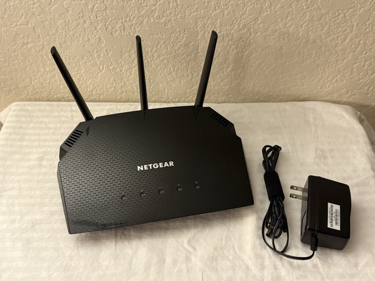
Dissasembly
I started with the obvious steps of taking it apart, there were 3 security screw holding the case together, there is a through-hole design mounting the PCB securely into the case. Once the 3 exterior screws were removed and the case cracked, I immediately noted a 4 pin header and had a suspect for serial connection. There was 3 other hardware points with potential for debug/extensibility, though no more on that for now.
The DRAM (DDR3), the main SBC CPU package, the ethernet controller were all located under a large heatsink. The heatsink was easy to remove with 4 chunky Phillips head screws holding it down exposing EMI shielding with thermal pads for the CPU & Ethernet Controller. Fortunately the EMI shielding was pressure fit and easy to remove without severely damaging. There was an additional chip with it's own EMI shielding directly adjacent the main SBC package, (I suspect this to be radio related though I did not note down the IC label as I already identified my main points of interest for now, this will probably come back to bite me).
Hardware packages:
- Broadcom BCM6755A1KFEBG, SoC
- Broadcom BCM531340KFBG, Ethernet Controller
- Winbond W634GU6NB-12, 4Gbit(512MB) DDR3L RAM
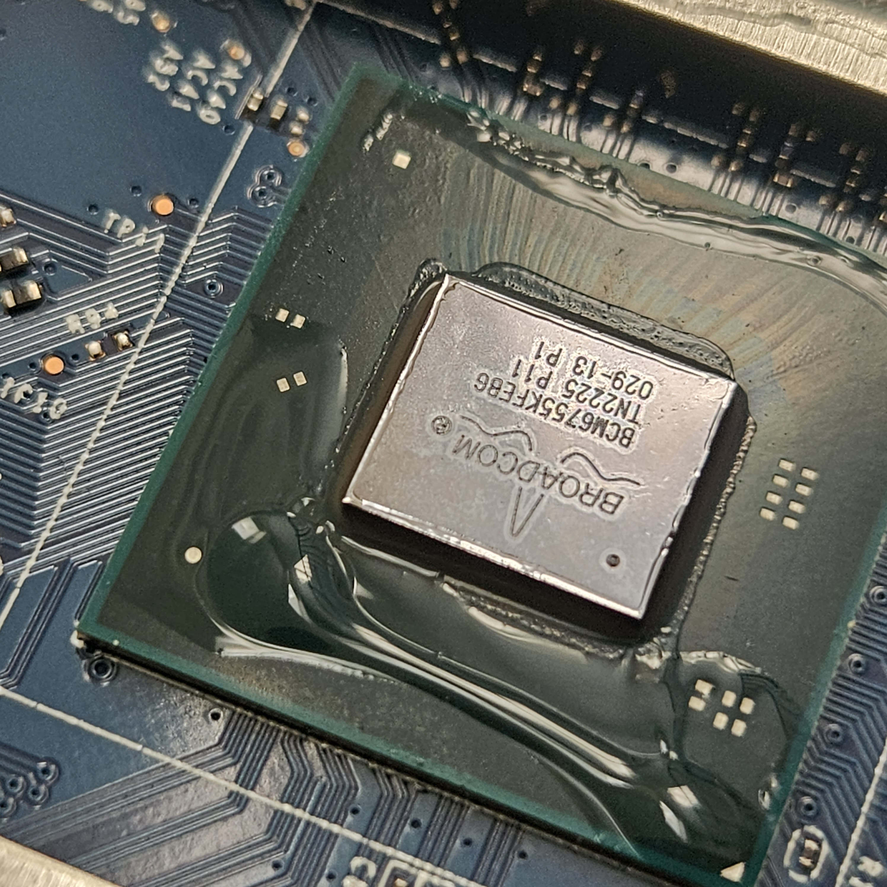
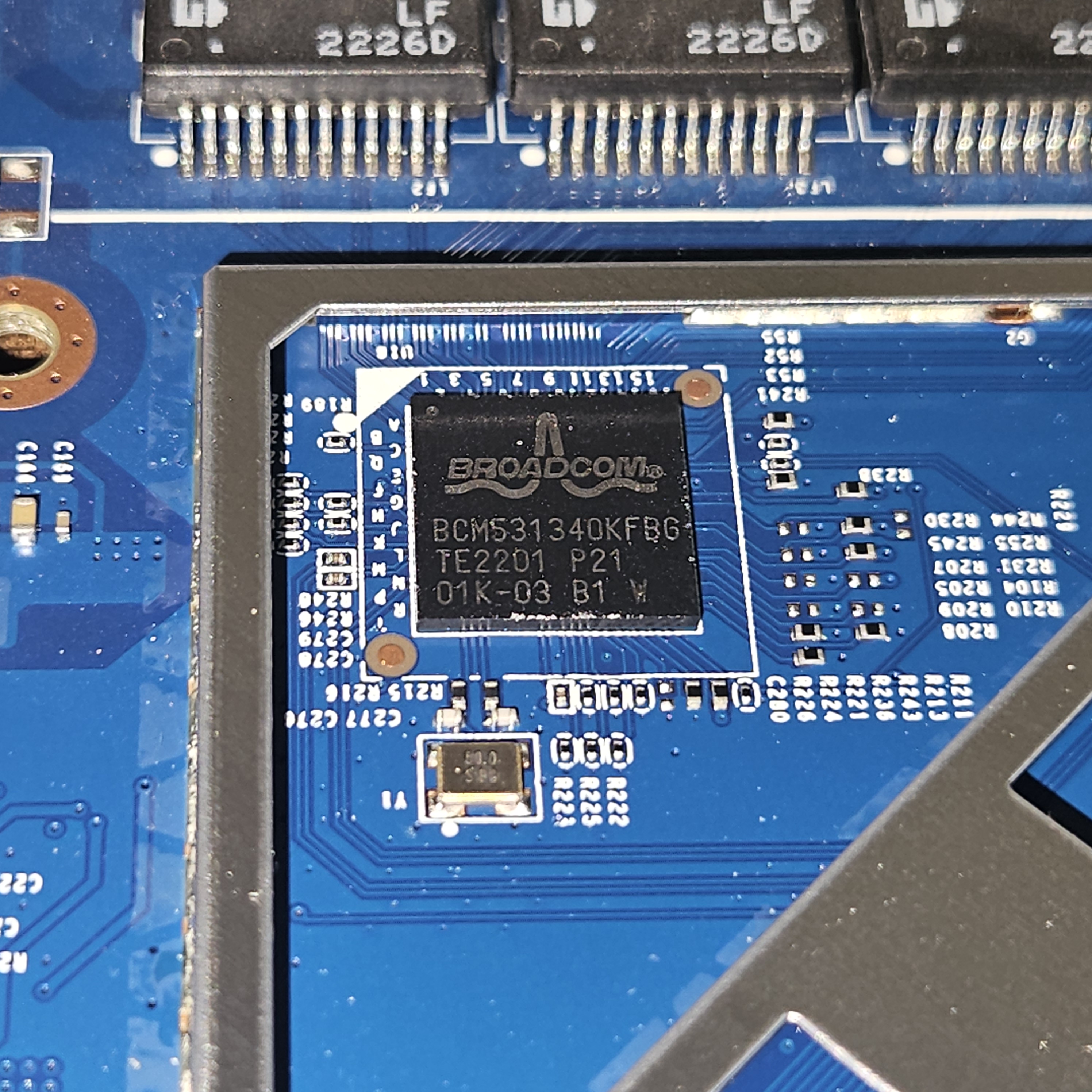
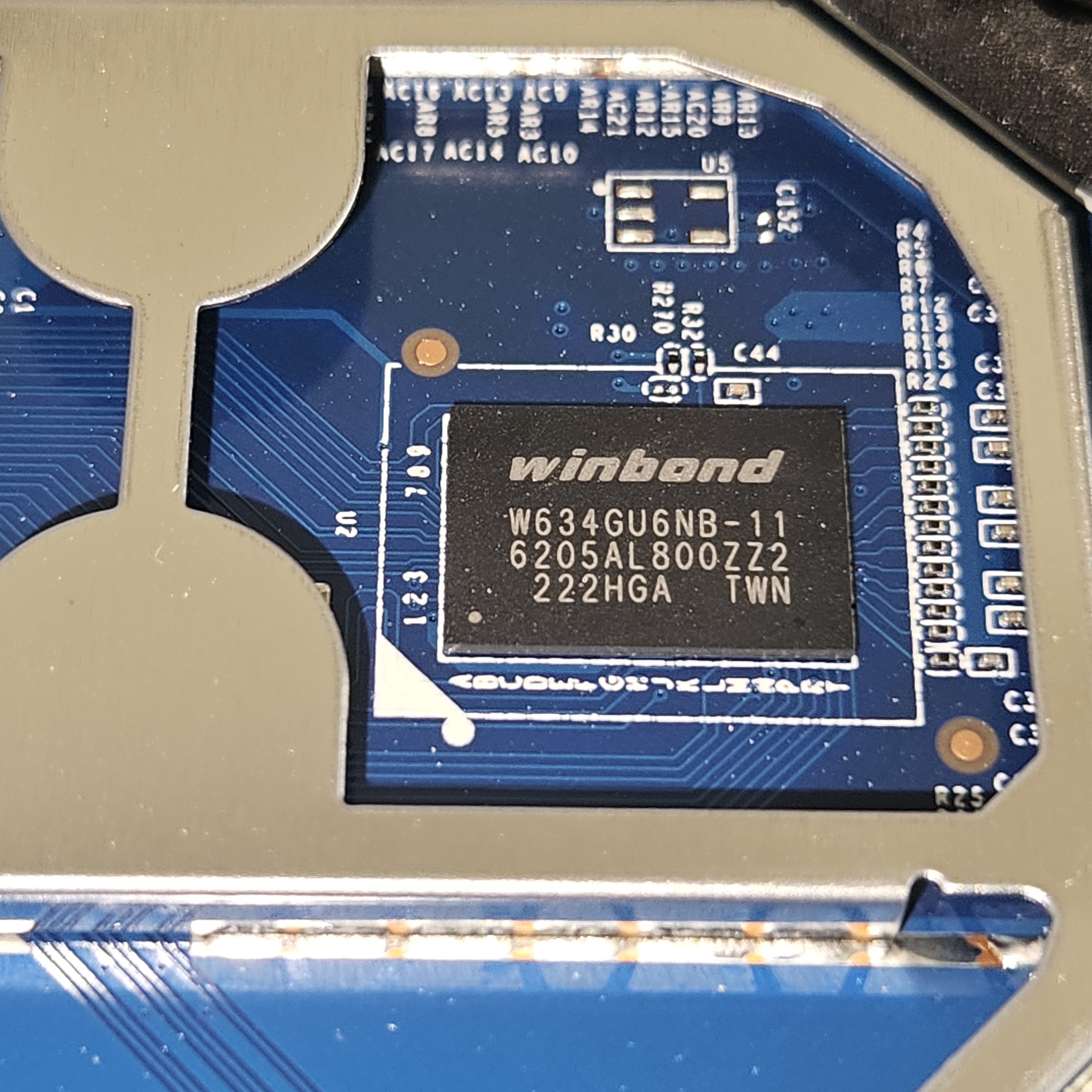
Seperate from the heatshield, we had the 256MB flash.
* Macronix 2Gbit(256MB) NAND MX30LF2G18AC
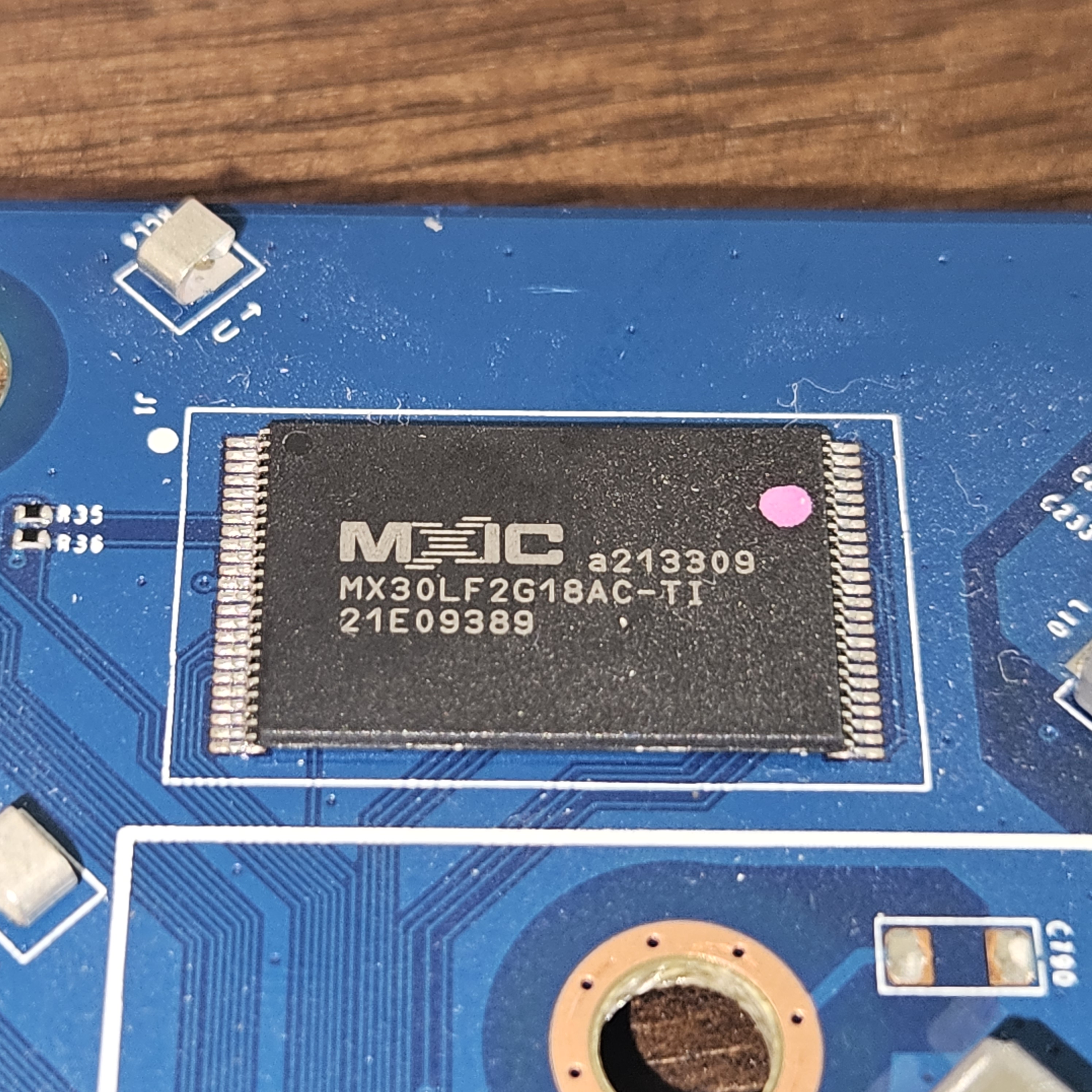
That means this is not a toy microcontroller router. It is a 1.5 GHz quad-core ARMv7 Linux machine with half a gigabyte of RAM, hardware packet acceleration, two PCIe Wi-Fi radios, and a slightly cursed 256 MB NAND-backed appliance filesystem; (The NAND is being managed/controlled by the host directly).
At this point I was ready to see if what I suspected to be a serial header, really was simply a serial header. I got my multimeter and identified voltage as 3.3v, I checked to see if there was any visible voltage change from transmission drops on any of the pins, quickly I identified pin 1 for TX this way (white), I connected it to a standard serial reader after confirming pin out as p0(3.3v) P1(TX) P2(RX) P3(GND), I connected TX, RX, & GND to my Pine64 serial console.
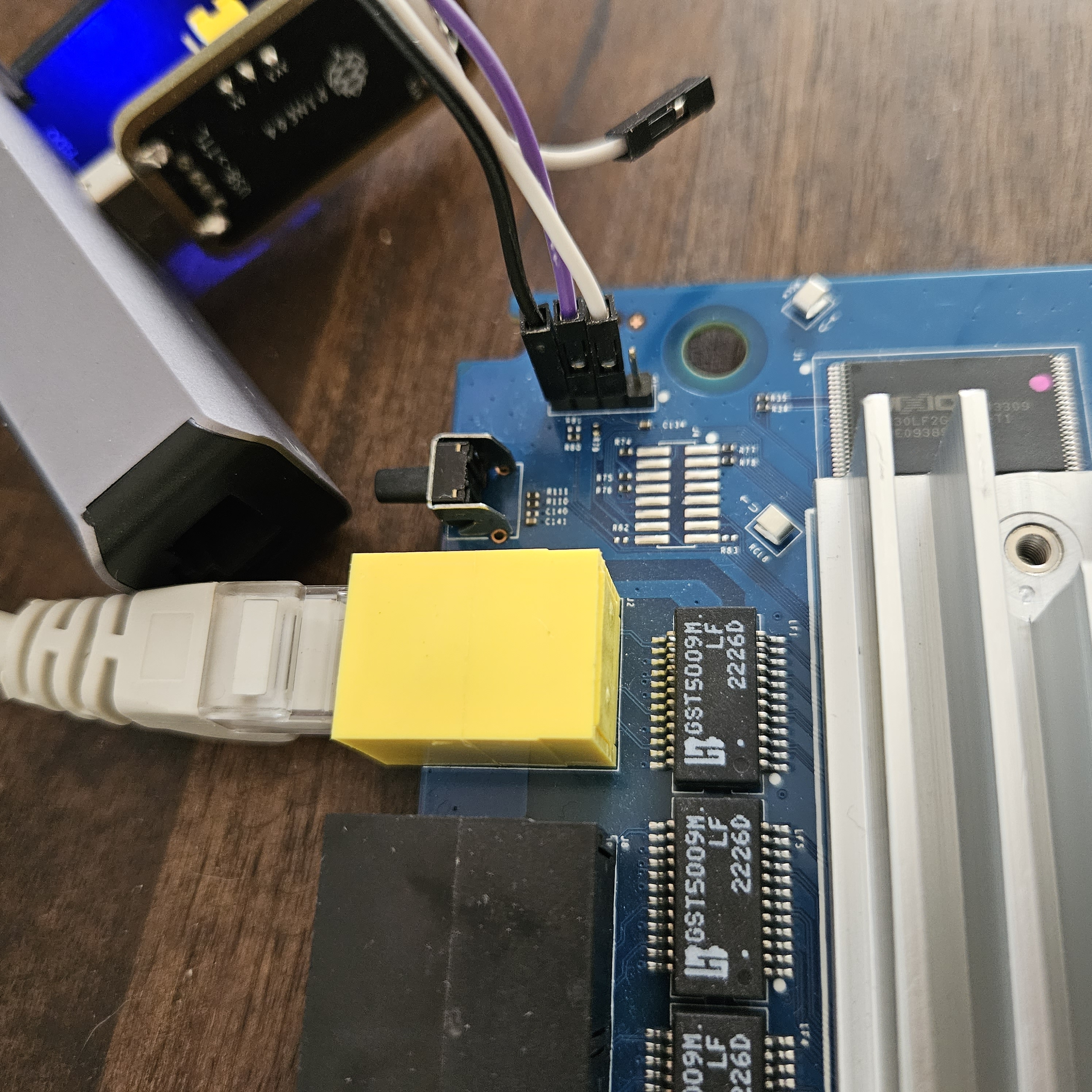
I rebooted and opened a standard serial terminal over the USB COM port @ 115200 Baud (115200 8N1), this caused a flood of coherent serial output leading me to re-assemble the EMI shielding and heatsink before the device got too hot.
The running hardware
The bootloader identified the platform as:
Chip ID: BCM6755_A1
ARM Cortex A7 Quad Core: 1500MHz
Total Memory: 536870912 bytes (512MB)
NAND flash: 256MB
The flash is SLC NAND with:
Page size:        2048 bytes
OOB/spare area:     64 bytes
Erase block:    131072 bytes / 128 KiB
ECC:            BCH-4
The boot chain
The serial console exposed the full chain:
Early bootstrap / BTRM
→ Broadcom CFE bootloader
→ CFE reads NAND and locates vmlinux.lz
→ CFE decompresses the Linux kernel
→ CFE loads a DTB
→ CFE patches boot arguments and NVRAM into the DTB
→ Linux boots
→ Linux mounts the SquashFS root filesystem
Identifying CFE lines were:
ubi_find_file: got vmlinux.lz  size 2756881
Decompression LZMA Image OK!
Entry at 0x00018000

cfe_fs_fetch_file: file RAX60.dtb not found
ubi_find_file: got 947622.dtb  size 4540

Setting ROOTFS: root=/dev/ubiblock0_0 ubi.mtd=0 ubi.block=0,0 rootfstype=squashfs
CFE appending "isolcpus=3" from PROFILE to boot cmdline
Appending CFE version to dtb
Appending NVRAM to dtb
This immediately explained something that confused me at first: the kernel is not stored in /boot, and it is not inside the root SquashFS filesystem. This brings me new questions though like why is the firmware expecting a different DTB than the one it provides? Why does it need to apppend the NVRAM? We find out later there is a mismatch between the DTB itself and the actual amount of memory installed, this is another thing that the CFE environment appears to be configuring. The verbosity of the serial output will help later though for seperating different firmware pieces with 0 guesswork.
Now we know CFE has its own tiny file store inside the firmware UBI image for boot files. It pulls the compressed kernel and DTB from there before Linux exists. Linux then mounts a separate SquashFS volume as /.
Storage: raw NAND is not a disk
The router’s storage stack is:
Raw NAND flash
→ MTD partitions
→ UBI
→ UBI volumes
→ either SquashFS or UBIFS
The important part:
mtd0 rootfs
→ UBI
→ ubi0:0
→ ubiblock0_0
→ SquashFS
→ immutable Linux root filesystem

mtd2 data
→ UBI
→ ubi1:0
→ UBIFS
→ mounted writable /data
This is why my initial NAND dump experiments were confusing. Raw NAND partition is not a normal disk image. It has erase blocks, bad blocks, ECC, UBI headers, wear-level metadata, and logical volumes. If a tool skips physical bad blocks while dumping, the resulting file can be perfectly useful as a stream of readable data while no longer lining up as a valid physical UBI image. This is something new to me as most of my prior successful projects with SBCs were not reverse engineered and all had more standard feeling storage stacks.
The router reported bad blocks inside the rootfs region:
nand_flash_read_buf(): Attempt to read bad nand block 480
nand_flash_read_buf(): Attempt to read bad nand block 591
nand_flash_read_buf(): Attempt to read bad nand block 593
nand_flash_read_buf(): Attempt to read bad nand block 792
That was the first major lesson:
A “raw flash dump” is only raw if you understand exactly how the dumper handled bad blocks and OOB data.
The easy firmware dump
The cleanest filesystem-level target was not /dev/mtd0.
It was:
dd if=/dev/ubiblock0_0 bs=1M | nc 10.69.69.120 9000
/dev/ubiblock0_0 is already the UBI volume presented as a block device for SquashFS. Dumping it skips the raw NAND and UBI bookkeeping layers entirely.
The first four bytes of the resulting image were:
68 73 71 73
 h  s  q  s
That is the SquashFS magic.
From there, extraction was straightforward:
unsquashfs -d RAX10-rootfs-extracted RAX10-root.squashfs
The extracted filesystem contains the normal Linux userspace:
/bin
/etc
/lib
/sbin
/usr
/www
That is where the interesting Netgear shell scripts, daemon binaries, web UI pieces, configuration helpers, and Broadcom modules live.
The official firmware image was much cleaner than expected
Running Binwalk on the stock update file showed:
0x00000080 UBI image
The first 128 bytes are a Netgear/DNI update header. Everything after that is a normal UBI image.
After stripping the 128-byte header and inspecting the UBI container, I found four volumes:
rootfs_ubifs       403 erase blocks
METADATA             1 erase block
METADATACOPY         1 erase block
filestruct_full.bin 26 erase blocks
Despite its misleading name, rootfs_ubifs starts with:
68 73 71 73
hsqs
It is a SquashFS image, not a UBIFS filesystem.
The important realization was:
rootfs_ubifs
→ SquashFS userland

filestruct_full.bin
→ CFE boot artifacts:
   kernel
   device trees
   boot metadata
Finding the actual kernel
Binwalk on filestruct_full.bin found:
0x0000001B  Device tree blob, 4540 bytes
0x000011F9  Device tree blob, 4724 bytes
0x0000248F  Device tree blob, 4724 bytes

0x0006C3E9  LZMA compressed data
            compressed size:   2757010 bytes
            uncompressed size: 7756064 bytes
That LZMA stream is the missing bootable kernel payload: vmlinux.lz.
The CFE boot log reported vmlinux.lz as 2,756,881 bytes, while Binwalk identified a 2,757,010-byte LZMA stream. The 129-byte difference is probably file-record or container overhead, but I have not fully decoded the CFE file-store format yet.
The kernel can be carved and decompressed with:
dd if=img-787591378_vol-filestruct_full.bin.ubifs \
   of=vmlinux.lz \
   bs=1 \
   skip=$((0x6C3E9)) \
   count=2757010 \
   status=progress

xz --format=lzma -dc vmlinux.lz > vmlinux
file vmlinux
The DTB was more revealing than expected
The first extracted DTB decompiled successfully:
dtc -I dtb -O dts -o dtb-0.dts dtb-0.dtb
The warnings were style warnings from Broadcom’s old device-tree naming conventions, not a failed decompile.
The DTS describes a generic Broadcom BCM947622 platform:
model = "Broadcom BCM947622";
compatible = "brcm,bcm947622";
It includes:
ARM Cortex-A7 CPUs
PL011 UART at 0xFF812000
NAND controller at 0xFF801800
I2C
PCIe
SDHCI controller
hardware RNG
crypto accelerator
watchdog
thermal support
The most interesting discovery was that the static DTB claims only 64 MB of RAM:
memory {
    reg = <0x00 0x4000000>;
};
But CFE patched the live handoff DTB to 512 MB:
/memory = 0x20000000 bytes @ 0x0
CFE also injected the actual root filesystem location, NVRAM, CFE version, and the isolcpus=3 performance setting.
So the static DTB is not the final board description. CFE turns it into one at boot.
CFE: the bootloader has a loaded gun labeled “e”
Interrupting boot drops into CFE. The discovery command was:
help
The reassuring commands include:
p               Print boot line and board parameters
cfe_version     Show CFE version
fb              Find NAND bad blocks
dn              Dump NAND contents including spare area
rn              Read NAND with ECC disabled
find            Find a string in NAND
comp            Compare NAND blocks
nmrp_flag_show  Show recovery flag
meminfo         Show system memory
The terrifying commands include:
e               Erase NAND flash
w               Write a whole image from the beginning of flash
ws              Write an image previously loaded through Kermit/JTAG
upgrade_cfe     Upgrade CFE
upgrade_image   Write a complete image
i               Erase persistent storage
factory_default Factory reset
The command name e literally means:
Erase NAND flash
Nice to know that the proprietary alternative to U-Boot is designed to be as user friendly as a .50cal rifle with a kink in the barrel.
CFE also exposes recovery hooks:
fw_recovery     start TFTP server
nmrp            start NMRP client
Those are likely the practical recovery path after a normal firmware brick. They are much more useful than attempting a blind raw-NAND restore.
Security state: unsecure does not mean unrestricted
One surprising CFE command was:
otpcfg get mode
Its result:
SoC is in unsecure mode
That is encouraging for experimentation, because the irreversible OTP secure-mode flag does not appear to be set.
It does not prove that CFE will accept arbitrary unsigned images. CFE may still enforce a Netgear header, board ID, checksum, version rule, or signature policy.
Also, this command should never be run casually:
otpcfg set mode secure
That sounds like an irreversible fuse operation, and I have no desire to discover exactly how irreversible.
The router repairs its own board data
One extracted script mirrors boarddata1 to boarddata2.
At boot, the router logged:
Start to handle the backup action, boarddata1 | boarddata2 ....
Both the data of origin and backup partition are good !!
The script checks both copies with dni_block_chksum. If the primary copy is valid and the backup differs or fails validation, the primary overwrites the backup. If the primary is bad and the backup is valid, the backup restores the primary.
The notable detail is that it copies only one NAND erase block:
nanddump ... -l 131072
flash_erase ...
nandwrite ...
That is exactly 128 KiB: one physical erase block.
This strongly suggests that the actual board-data object lives in the first good erase block of each 1 MB board-data partition. The remaining partition space is likely spare capacity or simply reserved by the vendor format.
It also means these partitions are not things to casually erase or overwrite. They likely contain device-specific identity, regional settings, MAC information, and other board configuration.
Where this leaves the project
At the end of day one, the router is no longer a black box.
I have:
✓ Root UART console
✓ Root Linux shell
✓ CFE shell
✓ Stock firmware container decoded
✓ Firmware SquashFS extracted
✓ Kernel location identified
✓ DTBs extracted and decompiled
✓ UBI volume structure mapped
✓ Boot flow understood
✓ A recovery path to investigate
✓ Several dangerous flash-writing helpers identified
Here are some of the things I may look into next:
- Dump the runtime DTB from
/sys/firmware/fdtand compare it to the static DTB. - Extract and inspect the decompressed kernel.
- Build a tiny static ARMv7 binary and run it from the router.
- Map every service listening on LAN interfaces before touching vulnerability research.
The interesting long-term idea is a hybrid system:
Stock CFE + vendor kernel/drivers
→ custom lightweight userspace
→ eventually a custom appliance-style firmware image
Ultimately since this device has it's home as a switch on my desk; the real challenge is preserving the vendor-specific pieces that make the switch, Wi-Fi radios, acceleration hardware, LEDs, watchdog, and flash layout behave.
For now, the router remains alive, bootable, and significantly less mysterious.